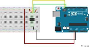
We first began our journey into learning the I2C protocol three weeks ago. In that post, we learned to write to an external EEPROM over the I2C protocol using nothing more than a datasheet and the Arduino’s built-in Wire library. Before learning to read from that EEPROM, which we will do today, we needed to gain the prerequisite knowledge of how data is stored in memory and how pointers work. From there, we learned how the data stored in these variables is passed along through to functions and what an array really is.
It’s been a daunting few weeks, but we’re finally there. Let’s read the data we wrote to our EEPROM armed with nothing more than the datasheet and the I2C protocol.
1. Review the Datasheet
Using the same strategy as before, we look for the command we’re interested in on the datasheet. Since we last wrote to the EEPROM using a page write, it should be pretty easy to guess that to read off our same data, we probably want a page read (also known as a sequential read).
Going to the Sequential Read section of the datasheet, we’re given the following description:
SEQUENTIAL READ: Sequential reads are initiated by either a current address read or a random address read. After the microcontroller receives a data word, it responds with an acknowledge. As long as the EEPROM receives an acknowledge, it will continue to increment the data word address and serially clock out sequential data words. When the memory address limit is reached, the data word address will “roll over” and the sequential read will continue. The sequential read operation is terminated when the microcontroller does not respond with a zero but does generate a following stop condition (see Figure 12 on page 12).Atmel: https://www.mouser.com/datasheet/2/268/doc0670-1180619.pdf
From here, the code practically writes itself, we just need to follow the directions Atmel has given us.
2. Write the Preamble:
Per the datasheet: “Sequential reads are initiated by either a current address read or a random address read.” Well, we wrote our data to a specific address, so we want to read from that address, so we’ll initiate the sequential read by using the random read. Referring to the Random Read section of the datasheet:
RANDOM READ: A random read requires a “dummy” byte write sequence to load in the data word address. Once the device address word and data word address are clocked in and acknowledged by the EEPROM, the microcontroller must generate another start condition. The microcontroller now initiates a current address read by sending a device address with the read/write select bit high. The EEPROM acknowledges the device address and serially clocks out the data word. The microcontroller does not respond with a zero but does generate a following stop condition (see Figure 11 on page 12). Atmel: https://www.mouser.com/datasheet/2/268/doc0670-1180619.pdf
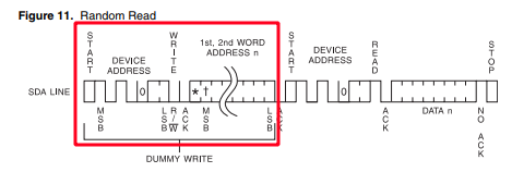
The above-boxed section represents the “the device address word and data word address are clocked in and acknowledged by the EEPROM” portion. We’ll start by coding this section. Thankfully, we’ve already done it in the Page Write post- it’s everything in section 2:
Wire.beginTransmission(0b1010000);
Wire.write(0b0000000); // 7 bits of 0s; this method takes a byte though so it will still transmit a byte's worth of 0s.
Wire.write(0b00000000);
Wire.endTransmission();
Boom. Header done.
3. Read the Data:
RANDOM READ: A random read requires a “dummy” byte write sequence to load in the data word address. Once the device address word and data word address are clocked in and acknowledged by the EEPROM, the microcontroller must generate another start condition. The microcontroller now initiates a current address read by sending a device address with the read/write select bit high. The EEPROM acknowledges the device address and serially clocks out the data word. The microcontroller does not respond with a zero but does generate a following stop condition (see Figure 11 on page 12). Atmel: https://www.mouser.com/datasheet/2/268/doc0670-1180619.pdf
The start condition (with sending a device address) is common to the I2C protocol and is thankfully handled by the Wire library with the simple Wire.requestFrom method, where the first argument is the device address and the second argument is the number of bytes to request from the EEPROM:
Wire.requestFrom(deviceaddress,2);Since I only wrote two bytes “Hi” to the address, I’m only requesting two bytes back.
Now to actually read the data, we’ll use a simple while loop:
while(Wire.available()) {
Serial.print((char)Wire.read());
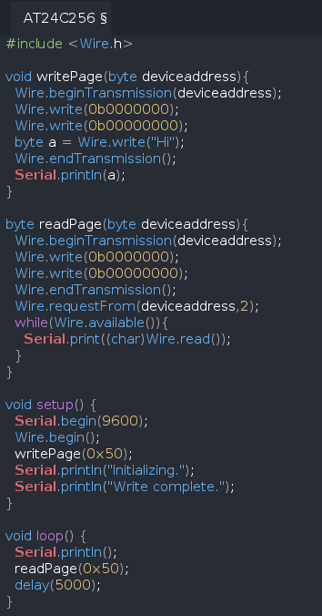
}Putting together the full code in its entirety from the past two tutorials:
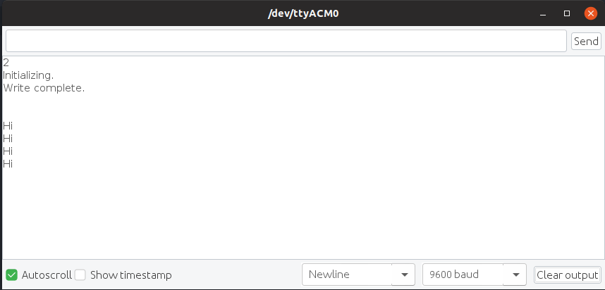
Here is what she looks like on the Serial Monitor:
In the future, we'll eventually revise this code to make it more versatile by putting it in a library.