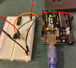
In a previous post, we covered how to expand your number of analog inputs by using an external ADC over the SPI bus. Today I want to demonstrate how to use the I2C protocol while simultaneously teaching you how to read a datasheet. After all, there will come a day when you want to use a new device and a library won't already exist for it.
First of all, let's establish the Arduino library we will be implementing to communicate with the AT24C256 EEPROM. For this tutorial, we will be using the Wire library to implement the I2C protocol (Mental shortcut: I2C protocol = Wire library). Let's begin!
1. Review the Datasheet
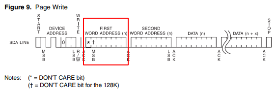
First, let's survey the land and have a look at the AT24C256 datasheet. When I look at a datasheet, one of the first things I do is figure out what commands I want to use. In this case, I know I want to do a page write. A page write allows you to write multiple bytes of data all at once, as opposed to a byte write which is all sorts of tedious. I'm a visual learner so once I know what command I want to use, I jump to the figure that parses it out. The figure for Page Write is shown below:
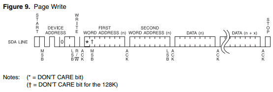
Just looking at this figure I see that every I2C message starts with three words: a device address, a first word address, and a second word address. This preamble is then followed with the actual data you want to write.
2. Writing Out the Code for the Address (i.e. the preamble)
From that diagram alone the code practically writes itself. It's just a matter of knowing which methods to call in the Wire library. Let's implement the code one word at a time:
Device Address
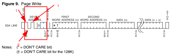
Focusing on this part of the diagram, we see that the device address begins with a 1 (the line is high), followed by a 0 (line is low), 1, and so on so that we ultimately end up with 0b1010000. The last two least significant bits (LSBs) are 0s but can actually be changed to allow for up to four of these EEPROMs to be on the I2C bus. This is also shown separately in the datasheet:
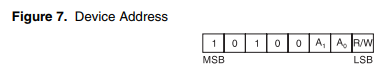
"But wait!" you say, "That's only 7 bits. A byte is eight bits. What gives?!"
Well, you are technically correct- to make the full byte, we should have an eighth bit that tells the device whether we want to read or write (the R/W in the LSB position shown above), but we are using the Arduino Wire library which expects a 7-bit address. If you are given an 8-bit address like in Figure 7 above, you need to bit shift one position to the right to get a 7-bit address. Notice that you don't have to do this minor bit of mental gymnastics if you just look at the original diagram in Figure 9. The Wire library will handle appending the R/W bit based on what method you end up calling.
So to begin our I2C transmission, we simply call the following:
Wire.beginTransmission(0b1010000);First Word Address
Let's just assume we're starting off with a blank slate. So we're just going to start from an initial address of 0. Honestly, we might as well go ahead and address the second word address here while we're at it. We can think of the first and second word address as one giant address: i.e. two bytes together (a.k.a. an int). Looking at where the MSB of this "giant" 16-bit would fit in the diagram above (where the * is), we see that this value is a "DON'T CARE BIT". Since I'm using a 256K EEPROM, our MSB for our address begins where the cross is (so we actually have a 15-bit address). Therefore our 15-bit address comes out to: 0b000000000000000 (i.e. 15 0's).
Getting back to the first word address, we can see that that the AT24C256 still expects a full 8-bit byte even if it doesn't particularly care what that first bit actually is. We can accomplish this with the following code:
Wire.write(0b0000000); // 7 bits of 0s; this method takes a byte though so it will still transmit a byte's worth of 0s.Second Word Address
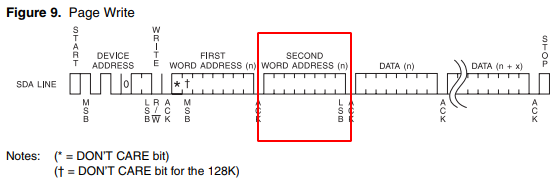
Now we just transmit the second word address (i.e. the remaining 8 bits of our 15 bits from above):
Wire.write(0b00000000);Granted this was a pretty trivial address, but I think you get the idea.
3. Write the Data
Now, I assume you probably didn't come here to just address the EEPROM. You want to actually write some data to it right? Well, now you can do that using the same Wire.write calls we've done before. We're finally in this part of the Page Write diagram:
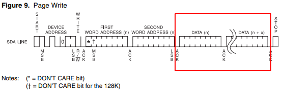
This part is rather simple compared to what we've done so far. To write data we simply use Wire.write again:
Wire.write(15);The beauty of using Page Write is that we aren't limited to just writing one byte at a time (which is what happens when you use Byte Write). With Page Write, once you've queued up the preamble, you can then queue up an entire array all at once. For example:
Wire.write("ABC");4. Putting It All Together
Putting it all together, the hard-coded Page Write function we just wrote could look something like this:
void writePage(){
  Wire.beginTransmission(0b1010000);
  Wire.write(0b0000000);
  Wire.write(0b00000000);
  byte a = Wire.write("Hi");
  Wire.endTransmission();
}
Don't forget the Wire.endTransmission(); at the end so that we actually send out our data over the I2C bus. Also don't forget to designate your Arduino as the master device in your setup block with Wire.begin();.
This tutorial has become a bit longer than I originally intended. Let's call it a night and we'll pick back up in the next post with how to request (read) data back off the EEPROM!