
Tutorial on creating VLANs from scratch and routing them on an L3 Switch with pfSense integration.
This site is getting more traffic than I had ever anticipated and, in order to support this self-hosted site and my homelab, I have upgraded to a 1 gigabit internet connection. In doing so, the bottleneck in my homelab network has shifted from the internet connection to the router itself.
As a reminder, my previous homelab consisted of a DMZ interface on pfSense firewall with a second DMZ router sitting directly behind it (i.e. the WAN of the DMZ router connected to the interface of the DMZ pfSense interface port). This obviously led to a double NAT situation that I had to handle but aside from that, this network topology had worked well for me. With the upgraded internet package though, I noticed that I was only getting half (~500 mbps) of my theoretical download speed. I was unsure if the bottleneck was in my pfSense router or my DMZ router (or if my ISP was lying to me). I had thought my pfSense router might be the bottleneck, but when I did my download speed tests, none of my CPU cores pegged to 100% (in a pfSense router with a dedicated quad port NIC, the bottleneck is most likely to occur in the CPU with heavy traffic as the firewall rules are evaluated), so I reasoned that the pfSense firewall being the bottleneck was unlikely. As a quick, field expedient test, I set up another interface on a free port on pfSense. Speedtesting directly on that interface gave me my full download speed, so I knew the bottleneck was downstream of the connection and was on my DMZ router (not surprising since that was a cheap router running DD-WRT).
As my homelab has grown considerably since I first started out, I decided this was the perfect opportunity to replace my DMZ router and upgrade to an L3 switch.
VLANs and Switching
First, let’s start off with what a switch is. You are probably most familiar with a cheap unmanaged switch that allows you to plug it into another ethernet port and effectively split it into an additional 4-8 ports. This is known as an L2 switch – basically all the devices connected to the switch are on the same network and can communicate with each other. The L2 switch accomplishes this by keeping a MAC address table to keep track of what device is on which port. It then switches packets based on their MAC address/port.
One of the greatest features of a managed switch is that it allows you to create what’s called a VLAN (a virutal LAN). A VLAN lets you divide up (subnet) your physical network into separate logical ones.
Why would you want to do this? Well, my biggest motivation is security. By separating out the network into VLANs, you can cordon off the individual VLANs from each other. As an example, let’s say you had a business and you offered guest wifi. You obviously wouldn’t want your guests to be able to connect to your network and be able to access all of your business PCs. With VLANs, you could create two separate VLANs: one for your guest wifi, and another for your business network. With VLANs on a simple L2 switch, devices on those two networks can’t talk to each other since the devices on the your guest wifi effectively live on a separate network from your business network and there’s no routing between them.
What’s an L3 Switch?
An L3 switch allows you to take this functionality of a managed L2 switch a step further. In all but the most simple scenarios (like the guest wifi/business one above), there are scenarios where you want those VLANs to be able to communicate with each other. An L3 switch takes the routing functionality of a router and offloads it to the switch itself, allowing the switch to route traffic between VLANs. So an L3 switch gives you the security through the principle of compartmentalization (via VLANs), while also allowing you to route traffic between those VLANs on the switch itself.
I headed off to Ebay and picked up the following HP 1910-24G for a whopping $30:
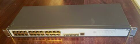
Even though this is the lowest price I’ve ever seen for this switch, it turns out I still overpaid (we’ll get to that later).
While you’re there, be sure to pick up a rollover (console) cable. Trust me, you’ll be glad you did, especially when the seller fails to factory reset the switch before shipping and won’t give you the password. I selected this particular cable because it had the best reviews and the most compatibility with other vendors, not just HP. This particular console cable worked great with my HP 1910.
1. Set Up Our Switch
So now we have our switch. Power it up and connect an ethernet cable between your PC and the switch. You’ll need to assign your computer a static IP since a DHCP server isn’t connected to the switch. The exact IP address you need to assign is based on the default IP listed on the back of the switch. For example, if the default IP on the switch is 192.168.254.12, assign your local PC an address of 192.168.254.20. The default subnet is 255.255.0.0. Navigate to the router’s default IP address in a web browser.
Alternatively, you can connect the switch directly to your pfSense firewall/router and the DHCP server running on pfSense will assign it an IP address. You can then just navigate to that assigned IP address (which can be found on the pfSense GUI or by running nmap over your local network).
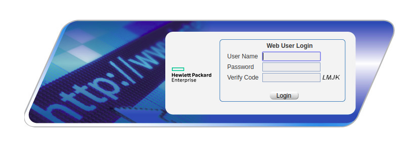
Once you navigate to the switch IP address, you’ll be presented with a login page. The default username is admin with a blank password:
2. Set Up Static Routing
The first thing we’ll do is set the switch up so that our VLANs can reach the internet. You see, by using the switch as an L3 switch, all routing is handled locally by the switch. The problem is, our switch’s router doesn’t know how to get to the internet- it isn’t directly connected to the internet, it’s never seen the internet before, it doesn’t know what the internet is. That’s what our pfSense router does, so we need to tell our switch about the pfSense router. We accomplish this by creating a static route. To do so, navigate to Network > IPV4 Routing > Create:
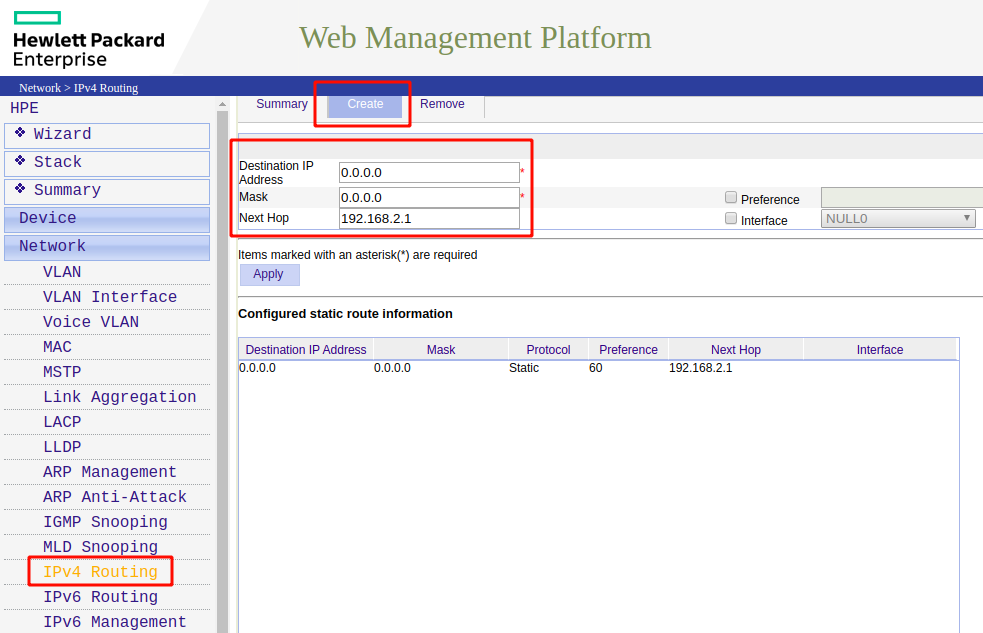
Enter a destination IP address of 0.0.0.0 with a mask of 0.0.0.0. The next hop should be the IP address of your pfSense router (in my case, it is 192.168.2.1).
So what have we done here? What we’ve said to our switch is that if we’re trying to access any IP address (0.0.0.0 with a mask of 0.0.0.0), get there by sending the traffic through our next hop at 192.168.2.1 (i.e. get there by going through our pfSense router). Preference is inversely related to how strongly we should use that route so by giving it a high preference, we’ll continue to use the other dynamic routes the switch’s router has picked up on if at all possible (i.e. so VLAN-to-VLAN traffic will continue to be routed through the switch).
Keeping along this same train of thought, the pfSense router has no idea how to get response traffic from the internet back to the VLANs since it has no idea of the VLAN’s existence. Therefore, we also need to define static routes on the pfSense route for the return traffic.
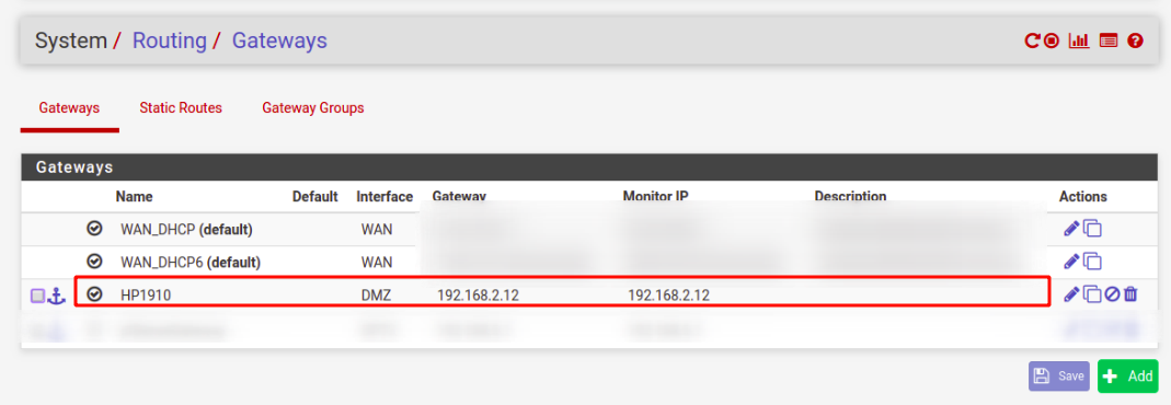
To do so, we need to first define a gateway in pfSense by going to System > Routing > Gateways. When you click add you will be prompted for an interface and a gateway IP address. But what interface and gateway IP address should we use? Thinking about the return flow of traffic, pfSense doesn't know how to get to our VLANs. It just knows it has traffic for an IP address it's never heard of. But there is one device that does know where the hosts that belong to these IP addresses live- the switch. And where does that switch live from pfSense's perspective? It lives in the DMZ. So we use the DMZ as our interface and we use the L3 switch's DMZ IP address as the gateway:
So now that we have a gateway specified, we can define the rest of our static route. Go to the "Static Routes" tab. You'll then specify the destination network, the interface, and the gateway (that we just created):
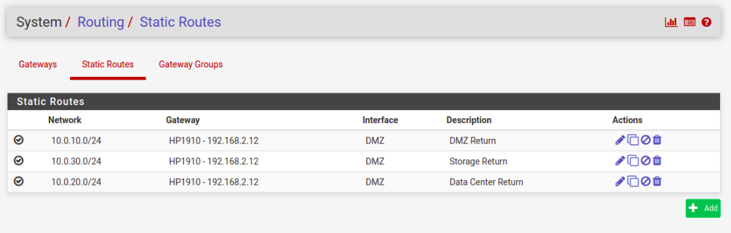
Let's summarize what we've done. The above static routes tell pfSense that for traffic destined for these networks, send the traffic through the DMZ interface, and use the L3 switch that's located on that DMZ interface as the "next hop" to route the traffic.
Test it out by changing the gateway (of your IPV4 settings) on your PC to the IP address of your switch. You should now be able to navigate to the web and ping outside servers. N.B. You may also need to update your firewall rules (see end of article).
3. Create Our VLANs
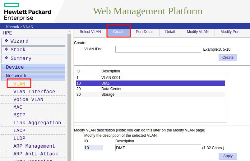
Now we’re finally ready to create our VLANs. Go to Network > VLAN > Create:
4. Assign Ports to Your VLANs:
We now need to tell the ports which VLANs they apply to. To do so, go to Network > VLAN > Modify Port:
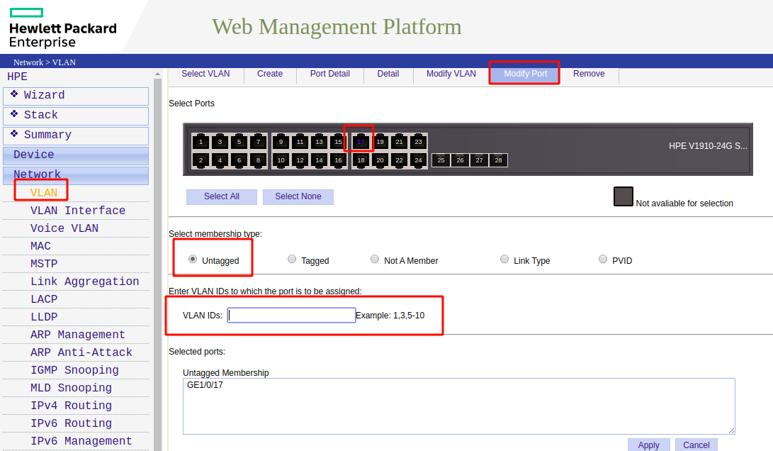
Select a port. Since the devices we’re going to connect to our switch aren’t “VLAN aware”, we are going to use an untagged port (meaning there is no VLAN tag added outbound on the port). In the VLAN ID box, specify the VLAN the device listed should be on.
5. Create VLAN Interface:
If we were going to use this switch as a simple L2 switch with our VLANs routed by our pfSense router (known as a “router on a stick” configuration), we wouldn’t need to complete this step. Creating the VLAN interface is what tells our HP 1910 switch to enable L3 routing. To create our VLAN interface, go to Network > VLAN Interface > Create:
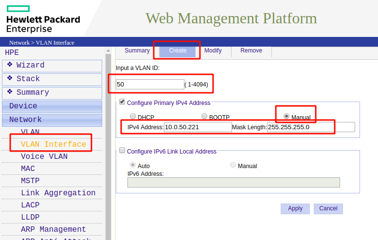
Input the VLAN ID you created in the previous step, select Manual for the IPv4 address (unless you have an external DHCP server you want to use). The IPv4 address you specify here will be the IP for switch on this VLAN. Since we’re using it as an L3 switch, this also means this address will be your gateway address for any devices you connect to this VLAN.
Don’t forget to click “Apply” and save often.
That’s it!
Don’t forget to assign the correct IP addresses and gateway for the devices you have connected to the switch. As a reminder, they should be in the same subnet as the VLAN specified on that port and their gateway should be the IP address of the switch itself on that VLAN (the one we specified in step 5). Example: If the VLAN interface is defined as 10.0.20.0/24 (worded another way 10.0.20.0 with a subnet of 255.255.255.0), then your IP addresses should fall within the 10.0.20.1-10.0.20.254 range.
You may also have to change your pfSense firewall rules on the interface that the L3 switch is plugged into. For example, you likely have a rule that says allow traffic originating from LAN net to anywhere. For our traffic to reach the internet, you would need to reconfigure this rule would need to allow traffic originating from anywhere to anywhere since our VLANs lie within a separate subnet.