
In Simon Monk's Programming Arduino Next Steps: Going Further with Sketches, Simon introduces the SPI protocol by way of interfacing the Arduino with a 10-bit ADC (specifically the MCP3008). Unfortunately, by choosing a 10-bit ADC to introduce the SPI protocol, he ultimately fails the main objective of getting students started with the SPI protocol. Additionally, without much explanation or reference to the MCP3008's datasheet, his implementation of the algorithm feels awkward and clumsy. Mostly because the code is just unintuitive.
In this tutorial, I offer an improved implementation of the SPI protocol (at least in terms of readability for the new learner) for interfacing a 10-bit ADC with an 8-bit microcontroller such as the Arduino. Additionally, I will attempt a more thorough explanation behind how the code works. This tutorial assumes an understanding of basic SPI protocol implementation (I'll save that for a future tutorial).
Background Information
First off, let's tease out the big assumptions. What does a 10-bit ADC mean? Simply put, it means that the analog-to-digital converter takes an analog voltage and represents it as a 10-bit digital value. What exactly does that mean? It means that it represents the analog input as a value between 0 (at 0 V) and 1024 (at saturation- i.e. your max voltage). Where does the number 1023 come from? Simple- it's the maximum value that can be represented in binary by 10 bits all set to 1: (2^9)+(2^8)+(2^7)+(2^6)+(2^5)+(2^4)+(2^3)+(2^2)+(2^1)+(2^0). Add them all up and you get 1023.
Now, why is that a problem with a microcontroller such as an Arduino? Arduino, like most microcontrollers, speak in 8-bit (i.e. byte)-sized words. If our master device (the Arduino) is speaking on over the SPI protocol in byte-sized words and the slave chip speaks back in 10-bit words, we have an offset problem. The Arduino is done talking after 8 bits but our 10-bit ADC still has two bits left to transmit.
Outlining a Rough Algorithm
As always, the best way to learn is by example. Let's start by taking a look at MCP3008's datasheet. Specifically read Section 5.0- Serial Communication and 6.1- Using the MCP3004/3008 with Microcontroller (MCU) SPI Ports.
Yeah, yeah, I know you aren't going to read them, but you really should, I promise you they're worth it. Here are the highlights:
The first clock received with CS low and DIN high will
constitute a start bit. The SGL/DIFF bit follows the start
bit and will determine if the conversion will be done
using single-ended or differential input mode. The next
three bits (D0, D1 and D2) are used to select the input
channel configuration. Microchip: https://cdn-shop.adafruit.com/datasheets/MCP3008.pdf
Terminology notes: CS = "Chip Select" (aka SS- "Slave Select" in SPI nomenclature); Din = MOSI (Master Output Slave Input) in SPI nomenclature.
From just this part of the datasheet, we can start thinking about how we want to implement our algorithm for getting data off the ADC over the SPI bus. We are told that the chip recognizes the start bit based off SS going low and the first high MOSI bit it receives. Therefore our code could look something like the following:
digitalWrite(chipSelectPin, LOW); // Select the ADC by setting SS low.
SPI.transfer(0b00000001); // Fire off the start bit.
Now that we've woken up the ADC, we need to tell it what we want. We know from our datasheet that the next bit the ADC expects to see is the mode selection bit- in our case, we want to pass 1 since we want single-mode. The remaining three bits the ADC expects to see are the analog input address on the ADC. In my example, I am using input 0 so the three-bit address is simply 000. Knowing this we can then simply add the following line to our code:
SPI.transfer(0b10000000);But wait, it turns out that our ADC will start responding and giving us an output within this byte, so we actually need what the transfer method returns. Therefore we need something more like this:
byte readingH = SPI.transfer(0b10000000);Now that we've told our ADC what we want, and we've even started to receive data from the ADC, we'll need to continue letting the ADC continue to speak its 10-bit message. We can accomplish this by flushing the ADC with a byte of zeros:
byte readingL = SPI.transfer(0b00000000);Now the question is, at what point in the transfer's output does an individual bit start to represent something useful? (A professor might ask this same question as, "What bit in the byte output is our MSB (most significant bit)?" You can read the paragraphs in the datasheet but honestly it's surefire path to driving yourself mad; speech is too imprecise. As usual, a picture is worth a thousand words:
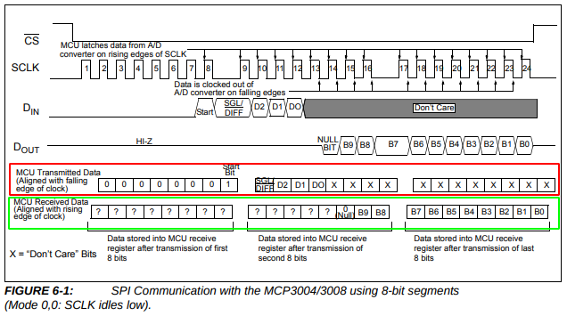
The part we're really interested in are the rows labeled "MCU Transmitted Data" (highlighted in red) and "MCU Received Data" (highlighted in green). This datasheet demonstrates the cleanest way to communicate with the ADC over SPI by using three one-byte words.
As you can see, we've already covered sending the first 8-bit word when we transmitted our start word (SPI.transfer(0b10000000);) and we have now just transmitted our controlByte (byte readingH = SPI.transfer(0b10000000);).
If you look at the corresponding byte (the second one) in MCU Received Data row, you'll see that the last two bits of that byte (readingH) are our MSBs: B9 and B8. We then flushed the ADC with our third byte with nothing but zeros to get the remaining 8 bits.
Now it's time to reconstruct the output message from the ADC in our Arduino. This can be accomplished with a combination of masking and bit shifting (You see?! Bit masking and shifting aren't just a useless academic exercise! They actually have a purpose!)
Starting with readingH we identified the MSB as being the last two bits. Therefore, we simply need to mask readingH as so with a bitwise & so we only get the last two bits:
readingH = (readingH & 0b00000011)Since these two bits represent the two most significant bits of our 10-bit value, we need to shuffle them over to the appropriate bit position with << 8.
readingL is even easier since the entire byte is the LSB. Now all we need to do is add readingH and readingL together to get our output. Remember, the data type of our addition operation is an int (i.e. two bytes) because we now have a 10-bit output. The whole operation can be done in a single line:
int reading = ((readingH & 0b00000011) << 8) + (readingL);Putting It All Together
Putting the above together in a single program:
#include <SPI.h>
const int chipSelectPin = 10;
void setup() {
Serial.begin(9600);
SPI.begin();
pinMode(chipSelectPin, OUTPUT);
digitalWrite(chipSelectPin, HIGH); //Immediately set CS (slave select) high so the ADC isn't selected on startup.
}
void loop() {
int reading = readADC(0);
Serial.println(reading);
delay(1000);
}
int readADC(byte channel){
byte startBit = 0b00000001;
byte controlByte = 0b10000000 | (channel << 4); // First bit 1 gives us single-ended mode on ADC; the next three bits represent the ADC's analog input
byte flushByte = 0b00000000; // Flush the ADC to get the remaining byte output.
digitalWrite(chipSelectPin, LOW); //Initiate SPI protocol by dropping slave select low.
SPI.transfer(startBit); // Fire off our start bit.
byte readingH = SPI.transfer(controlByte); // Push in our control byte which tells the ADC what mode to use and what channel we want.
byte readingL = SPI.transfer(flushByte); // Get the rest of our output from the ADC by flushing it with a byte of 0s.
digitalWrite(chipSelectPin, HIGH); // After flushing, immediately deselect the chip so that it doesn't continue.
int reading = ((readingH & 0b00000011) << 8) + (readingL); // Per datasheet, we know that only the last two bits of our first transfer contain useful info. The second byte is all useful.
return reading;
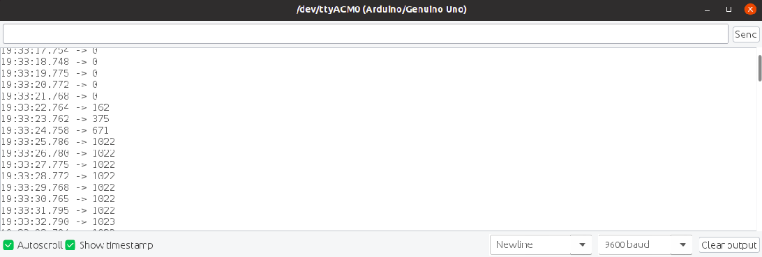
}When you pull up the serial monitor and start moving the potentiometer around, you should see something like this:
I hope this helps clear up any confusion with using the SPI protocol and especially when using a 10-bit ADC with an 8-bit microcontroller.